Measure at the ends, middle, and quadrant points, both high and low - 8 measurements and you will probably catch most deviations. Choose a tool that lets you do that, if these things matter. Tapered parallels, for example, are nice but tend to assume the slot has a single dimension.
Holes or slots in the arrow side member of a joint for plug or slot welding must be indicated by placing the weld symbol on the side of the reference line toward the reader (A, fig. 3-11).
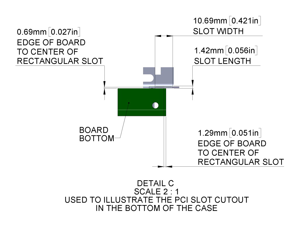
- What is the 'standard' method for dimensioning slots? We have for years located the slot by the geometric centerlines and described the slot size by note. For example: 'SLOT 9/16 X 1'. Some of us are wanting to locate the slot with the longitudinal centerline in one direction and by the ends of the slot in the opposite direction.
- Slot machines are popular gaming machines on every casino gambling floor and can range in types from the traditional reels machine to themed computerized slots and video machines. Slot machines range in dimensions but are traditionally around 30” (76 cm) deep and 74” (188 cm) high.
- When slots are intended to be used for holding only, tolerances can be 0.0 + 0.010 inch or H12 Metric (ISO/R286); when intended for location, tolerance can be 0.0 + 0.001 inch or H8 Metric. Corners of T-Slots may be square or may be rounded or broken to the indicated maximum dimensions at the manufacturer's option.
Holes or slots in the other side member of a joint shall be indicated by placing the weld symbol on the side of the reference line away from the reader (B, fig. 3-11).
Neither the plug weld symbol nor the slot weld symbol may be used to designate fillet welds in holes.
Plug or Slot Weld Diagram
Arrow Side & Other Side Indication of a Slot or Plug Weld Symbol
Slot or Plug Welding Symbol
Plug & Slot Welds Indicated by Arrow on Side of Joint

Plug Weld Dimensions
Dimensions of plug welds must be shown on the same side of the reference line as the weld symbol. The size of a weld must be shown to the left of the weld symbol.
The included angle of countersink of plug welds must be the user’s standard unless otherwise indicated.
The included angle of countersink, when not the user’s standard, must be shown either above or below the weld symbol (A and C, fig. 3-34).
The pitch (center-to-center spacing) of plug welds shall be shown to the right of the weld symbol.

Dimensions, Details and Surface Contour of Plug or Slot Welds
Depth of Filling of Plug and Slot Welds
Depth of filling of plug and slot welds shall be completed unless otherwise indicated. When the depth of filling is less than complete, the depth of filling shall be shown in inches inside the weld symbol (B, fig. 3-34).
Surface Contour of Plug Welds and Slot Welds
Plug welds that are to be welded approximately flush without recourse to any method of finishing must be shown by adding the finish contour symbol to the weld symbol (fig. 3-35).
Plug welds that are to be welded flush by mechanical means must be shown by adding both the flush contour symbol and the user’s standard finish symbol to the weld symbol (fig. 3-36).
Slot Weld Dimensions

Passport slots availability in bangalore. Dimensions of slot welds must be shown on the same side of the reference line as the weld symbol (fig. 3-37).

Plug Weld Dimensions
Dimensions of plug welds must be shown on the same side of the reference line as the weld symbol. The size of a weld must be shown to the left of the weld symbol.
The included angle of countersink of plug welds must be the user’s standard unless otherwise indicated.
The included angle of countersink, when not the user’s standard, must be shown either above or below the weld symbol (A and C, fig. 3-34).
The pitch (center-to-center spacing) of plug welds shall be shown to the right of the weld symbol.
Dimensions, Details and Surface Contour of Plug or Slot Welds
Depth of Filling of Plug and Slot Welds
Depth of filling of plug and slot welds shall be completed unless otherwise indicated. When the depth of filling is less than complete, the depth of filling shall be shown in inches inside the weld symbol (B, fig. 3-34).
Surface Contour of Plug Welds and Slot Welds
Plug welds that are to be welded approximately flush without recourse to any method of finishing must be shown by adding the finish contour symbol to the weld symbol (fig. 3-35).
Plug welds that are to be welded flush by mechanical means must be shown by adding both the flush contour symbol and the user’s standard finish symbol to the weld symbol (fig. 3-36).
Slot Weld Dimensions
Passport slots availability in bangalore. Dimensions of slot welds must be shown on the same side of the reference line as the weld symbol (fig. 3-37).
Details of Slot Welds
Length, width, spacing, included angle of countersink, orientation, and location of slot welds cannot be shown on the welding symbols.
Ansi Slot Dimensioning
This data must be shown on the drawing or by a detail with a reference to it on the welding symbol, in accordance with location specifications given in paragraph 3-7 (D, fig. 3-33).

